en
en cz
cz ru
ruQuestion 1: What are the main functional parts of a hydrogen filling station for road transport?
Answer: A hydrogen filling station (hereinafter referred to as HFS) is a complex, specialized technical device operating with hydrogen at high pressures, up to 900 bar. HFS ensures compliance with technological processes, taking into account all the chemical and physical properties of hydrogen and operational safety when fuel is supplied to a vehicle.
The main functional components of the HFS:
1. The basic part of the HFS is the hydrogen supply system to the HFS itself. Typically, the working stock pressure is about 25 bar.
2. Compressor unit designed to increase the hydrogen pressure. From the working stock, with a pressure of about 25 bar, hydrogen is pumped (using a compressor unit) into high-pressure buffers (hereinafter referred to as HPB), which are designed to provide the pressure required for fuelling the vehicle. However, if necessary, the input of the compressor unit can be re-connected to the output of the buffer of the first stage of the cascade. In this case, the compressor will compress the hydrogen to higher values (for example, from 300 bar to 500 and even 900 bar). The meaning of the concept of cascade pressure increase is to reduce the energy consumption of the process and limit the unwanted heating of the medium during the compression process (the equation of state with an initial temperature of 15 ° C is applicable to the filling of the buffer tanks).
3. HPB included in a multistage cascade. Each stage of the cascade consists of high-pressure cylinders connected in such a way that they form the required volume.
The hydrogen in the BVD under operating pressure represents the operational fuel reserve at the filling station, which serves to accelerate the process of filling of the connected vehicle.
Customer requirements for a gas station include, among other things, a description of the types of vehicles to be refuelled at a given station (for example, buses with a filling pressure of 350 bar and a tank capacity of about 30 kg of hydrogen or cars with a refuelling filling of 700 bar and a capacity tank about 6 kg), as well as the frequency and requirements for the filling rate (for example, the transport company owns 15 buses that must be filled within 3 hours, and also, in the future, expects to fill 5 more cars per day). Based on these data, the required operating pressure of hydrogen in the HPB is calculated, as the division into pressure levels of the cascades (for example, levels of 300, 500 and 900 bar).
4. Valve block with the control system, which controls the outlet of the compressor unit and thus allows the individual stages of the high-pressure buffer cascade to be gradually filled. The main variables influencing the operation of the valve block are the pressure in the cascade section and the temperature of the cylinders. Also, the control system controls the hydrogen by-pass through automatic valves between the individual pressure sections. The control variable in this case is the pressure in the vehicle tank and the hydrogen flow rate through the mass flow meter (an integral part of the dispenser stand. When the pressure in the buffer falls below the set minimum, and as a result, the flow of the medium decreases, the system will switch to another section of the buffer with a higher working pressure). In the case of filling at a pressure of 700 bar, the temperature of the filled tank is also taken into account.
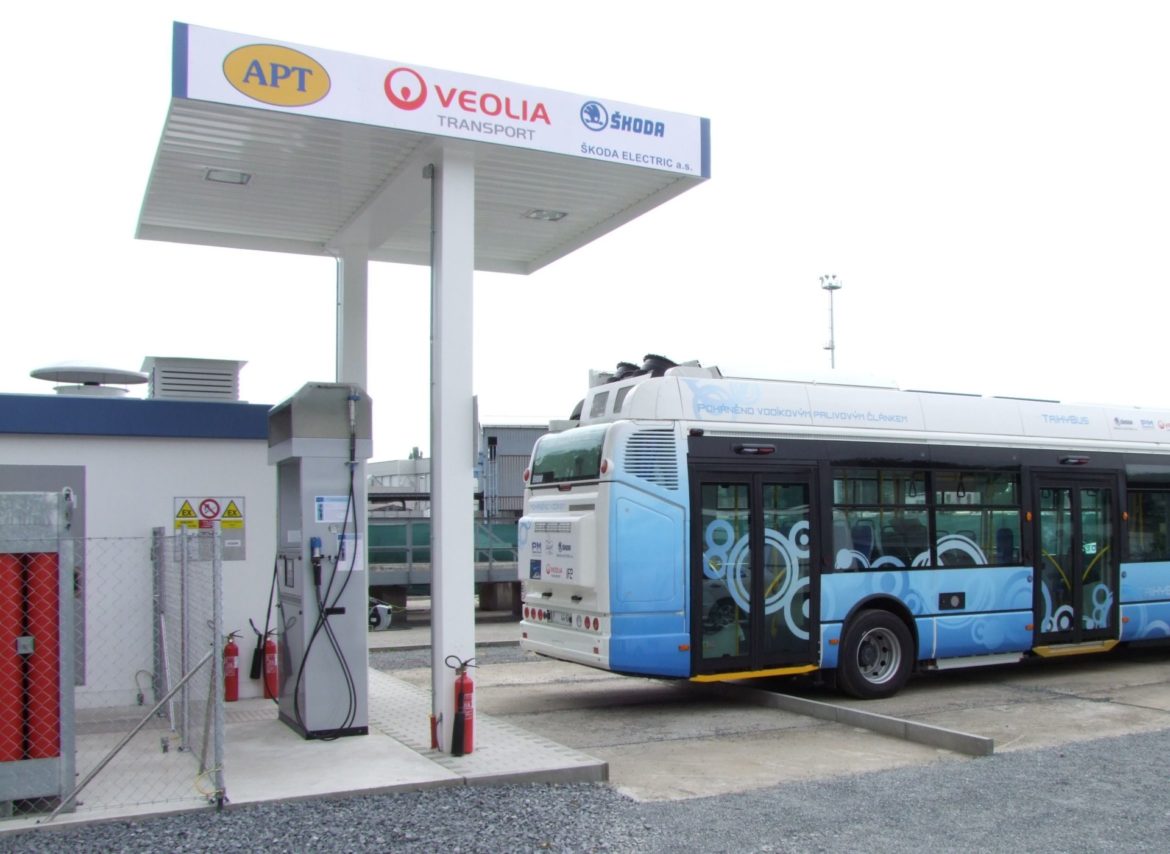
5. Dispenser – a device for the controlled supply of hydrogen to the vehicle tank. The dispenser performs several functions at once, in particular – ensuring the safety of the filling process (tight connection with the intake neck of the vehicle tank, tightness of the system itself, preventing damage to the hose, limiting the hydrogen consumption rate to 60 g / s, monitoring the pressure and temperature of the vehicle tank). In addition, the dispenser functions as a control system sensor for switching sections of the buffer cascade, as a commercial measurement for determining the fuel price, and also provides hydrogen cooling during filling at 700 bar. In this case, the dispenser unit is able to lower the temperature of the pumped fuel down to -40 ° C. The device is equipped with a banking terminal for payment and a registration system for drivers and filled vehicles.
6. The control system controls all processes taking place at the filling station. The system evaluates the information received from the sensors and maintains the technological process within the established operating limits. If any of the parameters is exceeded, the control system initiates an automatic sequence of actions aimed at bringing the station to a safe state. It communicates with the outside world, provides communication with higher-level control and monitoring systems, supports remote maintenance and self-diagnostics.